I have been working with OpenGL on Android for a month and would like to share what I have learned so far. I will go through the main parts of the OpenGL specicode and explain a bit about the different pieces.
When using version OpenGL ES 2.0, keep in mind that it is not backwards compatible with earlier versions such as 1.0 and 1.1. OpenGL ES 2.0 is supported by the Android platform since version 2.2.
There are two sides of the coin so to speak. The client and the server. The client is the software that resides on the CPU side and the server can be seen as the software running on the GPU. So, on the client side you have the choice of developing your application in either Java or go native or mix. On the GPU side you will write vertex and fragment shaders that will execute in the programmable vertex processor or fragment processor on the GPU.
Now, open up the OpenGL ES 2.0 Reference page. It's a great source of information of what is available :
http://www.khronos.org/opengles/sdk/docs/man/
Since I have not been using native code, the content on the reference page does not always match all OpenGL commands which are available on the application level. It's a bit annoying but there isn't actually more to it than that since Eclipse nicely auto completes for you and gives hints on the methods available.
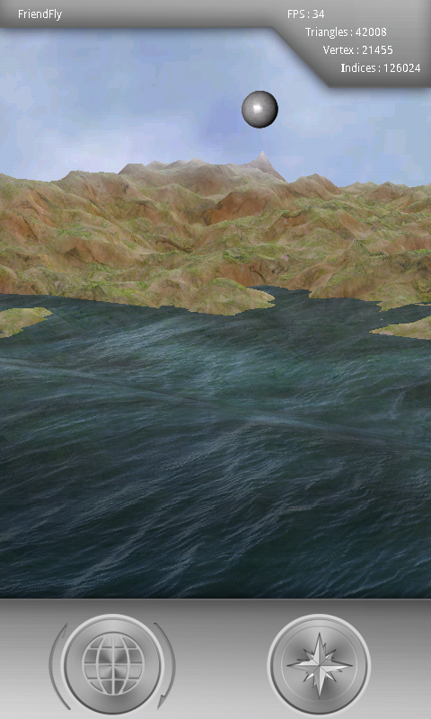
Some word on what I have done so far as the steps to get familiar with OpenGL using Android. A “world” made up from 42008 triangles from 21455 vertices and 126024 indices running smooth (32 - 59 fps) on my phone. The world is basically a fractal generated terrain based on the plasma algorithm also known as the diamond-square algorithm. The terrain has multiple textures (grass, snow, rock etc) which is applied to the terrain using a shader. A sun is circulating around the world casting shades depending on sun position. The ocean has waves with texture stretching, light effects, deep “water blackness”, normal mapping and alpha transparency all done in a another shader. There is a skybox with clouds moving around “effect”. A Waveform reader/parser to be able to easily drop files from Blender 3D into the assets folder. Overlaid SurfaceView with GLSurfaceView for a HUD containing controls and various information as FPS etc. Multi touch for game alike strafe (adsw) and turning (mouse equivalent). Camera model for walking/fly around in the world. I have constant movement irrespective of FPS and frame control filtering for a smoother experience.
In this tutorial the focus have been on a quite low level going through OpenGL API usage. The next thing in my opinion would be to implement a scenegraph to get structure, flexibility and ease of use.

Transformations are fundamental in OpenGL. It is described in every book and in a lot of places on the web. Instead of rewriting this part I will just refer to this page to start reading about transformations. If you already are familiar with the concept, just skip it and go on reading.
GLSL Programming/Vertex Transformations
I use the modelmatrix to transform objects from local/object space to world space and the viewmatrix to control the view (camera). Combining these two matrices gives you what could be called the modelview matrix. This way you can choose if you want to work in world (what you get when transforming from local space using the model matrix) or eye space (what you get when transforming from world space using the view matrix) in the shaders by providing both the model and view matrix.
I have a short lightning example below to show the differences between world and eye space. It is the lightning of the sphere that is placed above the peak.
To start with, the sphere that is being drawn have been constructed (in local coordinates) and setup/defined to be translated and rotated a bit so that it will be positioned into the world just above the peak. I have also defined a light source positions (in world coordinates) affecting the sphere. Now the position of the viewer and the way he/she is facing is contained in the camera model from which I create my view matrix to translate and rotate the world into the scene you see in the screenshot.
The vertices and normals of the sphere are defined in local space and are given as input to the vertex shader.
World space in the shader
Eye space in the shader
If you compare line 17 (world) and 21 (eye) you see that in worldspace I need to provide the position of the player (camera) but in eye space it's not needed since the camera is a origin. What this line does is to calculate the dot product between the "reflection vector from the vertex of the sphere" with the "vector from the vertex of the sphere to the player/camera". This value is then used to set the specular component of the light (the bright white area).
If you compare line 7 (world) and 9 (eye), you see that the vertex is transformed from local space to worldspace using the model matrix. To transform the vertex to eye space the modelview matrix is used.
If you look at line 12 (world), you see that the light direction is based on the light position which I defined in world space in the client with the worldspace vertex.
If you look at line 15 (eye), you see that the light direction is based on the lightposition in eye space (needed to transform the lightpos from world to eye space using the view matrix) and the vertex in eye space.
Now regarding the normals transformation of the sphere in eye space I am using the rotation part of the modelview matrix. This is fine as long as you don't apply any non uniform scaling during you transformations in which case you would need to use the inverse transposed modelview matrix instead.
The normal transformation in world space is similar, it's just that I have passed in a normal matrix which is based on the model matrix.
Shader program
Time to get hands on and set the base for creating shader programs. In OpenGL ES 2.0, to be able to draw anything, one must use a shader program. A shader program consists of compiled and linked vertex and a fragment shader source code. This code you write yourself. See them as C-alike programs with specialized vector and matrix data types available as well as special instructions for calculations that you normally do in a GPU. You compile them separately (the vertex and fragment shader) and then link them together into a usable shader program. This is actually very simple given the OpenGL API. Everything in this chapter boils down into basically one thing and that is to be able to issue the following command during drawing.
with a valid shader program ID.
Second step is to provide the source code for the shader
The third and final step is to compile to shader code which is simply done the following way.
The above can be wrapped into a method doing the three steps above with some error checking.
Since the shader code is provided as a string you can of course just write your shader code into a String. However, I placed the shader codes in the assets folder and just reading the files using the following method.
Linking the vertex and fragment shader into a shader program
By now, we have separately compiled the vertex and fragment shader and obtained ID's for them (glCreateShader). Now it's time to link these together to form a shader program. So to start, we need to create an empty shader program.
I have a minimum number of attributes and uniforms as a requirement for a shaderprogram, which is shown below. You might wonder where the view and perspective matrices are? Since the camera class is part of my transform class, the view and perspective (or orthographic) matrix uniforms are handled in the transform class instead. This works out nicely since it's common to all shapes and shaders. Note that since I am using multiple shaders, I need one additional step to first get the uniform location for the view and perspective matrices for the specific shader that will be used and then provide the uniforms to the shaderprogram (this last part is needed anyway).
I will touch upon the attributes and uniforms later in more detail but I wanted to put the code here for the sake of completeness.
Shader manager
You could create specific shaderclasses for your shaders by subclassing the shaderprogram instead and that way collect the specific attributes and uniforms in the derived class instead (instead of handling the "extra" attributes in your shapes). I had this approach in the beginning but it felt like an unnecessary level since the shader and the shape was quite tightly coupled. But I guess while the program is evolving you might want go down this road eventually. The question is sort of similar to what the minimum shaderprogram requirement should be as well. Note that even if textures are part of the minimum requirement, I still have options to turn on and off textures, and normals for example.
Here is the shader manager code.
There is an extension called GL_ARB_sampler_objects that allows you to have the same texture image data with different configurations (that is different texture names). This extension is not available in OpenGL ES 2.0 though (it is available on the desktop OpenGL 3.2 version). This means that if several shapes are using the same texture image but different repeat factors (for example) you would need to change the repeat factor in between the drawings (or duplicate the texture image into several texture names).
Here is the complete method for loading a texture and creating a texture for future use.
According to OpenGL specifications the matrix should be 16 value arrays with base vectors laid out contiguously in memory and the translation components occupy the 12th, 13th, and 14th element. The OpenGL Specification and reference manual both uses column-major notation so that's what I am going to use as well. Visualized as seen below. (Note that you could use row-major notation instead but you would need to perform your multiplication the other way around with “row vectors” instead.)
What glBufferData is doing is to “create and initialize a buffer object's data store”. If we would have used a null pointer as the third argument, no copy would have been performed. The size is specified in bytes. GL_STATIC_DRAW is a hint to OpenGL on how the buffer will be used. In my case I will not change the data. This is just a hint, you still have the possibility to change it but then it would have been better to set it to GL_DYNAMIC_DRAW instead. Note that for the indices we are binding to the GL_ELEMENT_ARRAY_BUFFER and in the other cases to GL_ARRAY_BUFFER.
Besides preparing this information for the glDrawElements, I also need to copy the model matrix and my normal matrix to the shader.
Here is the complete draw method. Note that I am disabling the vertex attrib arrays after glDrawElements to prevent the next draw from mistakenly using them.
Only one part left to explain in the draw method, the useTextures() method which is called in the beginning. Remember that we have created texture names already (which we saved in texture packs). Now it's time to utilize them. But first, we need to select a specific texture unit to use. When this is done, the selected texture unit will be affected by any subsequent calls that change the texture state.
Secondly, we use our texture name. What we will do is to bind the texture name to a texture target of the current active texture unit. Since we already have made configurations to our texture name, they will be used here.
The third step is to just specify which texture unit the sampler in the shader should use by using glUniform1i with the location and the texture unit as parameters.
Summary
I hope that you got some ideas and/or help from reading this blog to get your fundamental OpenGL ES 2.0 for Android setup in place. As I wrote in the beginning, the next thing to think about is incorporating a scenegraph. With a scenegraph you get some really nice flexibility and ease of usage when building up more complex scenes/worlds.
When using version OpenGL ES 2.0, keep in mind that it is not backwards compatible with earlier versions such as 1.0 and 1.1. OpenGL ES 2.0 is supported by the Android platform since version 2.2.
There are two sides of the coin so to speak. The client and the server. The client is the software that resides on the CPU side and the server can be seen as the software running on the GPU. So, on the client side you have the choice of developing your application in either Java or go native or mix. On the GPU side you will write vertex and fragment shaders that will execute in the programmable vertex processor or fragment processor on the GPU.
Now, open up the OpenGL ES 2.0 Reference page. It's a great source of information of what is available :
http://www.khronos.org/opengles/sdk/docs/man/
Since I have not been using native code, the content on the reference page does not always match all OpenGL commands which are available on the application level. It's a bit annoying but there isn't actually more to it than that since Eclipse nicely auto completes for you and gives hints on the methods available.
Some word on what I have done so far as the steps to get familiar with OpenGL using Android. A “world” made up from 42008 triangles from 21455 vertices and 126024 indices running smooth (32 - 59 fps) on my phone. The world is basically a fractal generated terrain based on the plasma algorithm also known as the diamond-square algorithm. The terrain has multiple textures (grass, snow, rock etc) which is applied to the terrain using a shader. A sun is circulating around the world casting shades depending on sun position. The ocean has waves with texture stretching, light effects, deep “water blackness”, normal mapping and alpha transparency all done in a another shader. There is a skybox with clouds moving around “effect”. A Waveform reader/parser to be able to easily drop files from Blender 3D into the assets folder. Overlaid SurfaceView with GLSurfaceView for a HUD containing controls and various information as FPS etc. Multi touch for game alike strafe (adsw) and turning (mouse equivalent). Camera model for walking/fly around in the world. I have constant movement irrespective of FPS and frame control filtering for a smoother experience.
In this tutorial the focus have been on a quite low level going through OpenGL API usage. The next thing in my opinion would be to implement a scenegraph to get structure, flexibility and ease of use.
Transformations
GLSL Programming/Vertex Transformations
When dealing with transformations and different spaces just remember (at least) one thing, which ever space you choose to work in, make sure that all your entities you are doing calculations on are in the same space. I like to work in world space when doing shader calculations but I guess it depends on what kind of application you are doing as well.
I have a short lightning example below to show the differences between world and eye space. It is the lightning of the sphere that is placed above the peak.
To start with, the sphere that is being drawn have been constructed (in local coordinates) and setup/defined to be translated and rotated a bit so that it will be positioned into the world just above the peak. I have also defined a light source positions (in world coordinates) affecting the sphere. Now the position of the viewer and the way he/she is facing is contained in the camera model from which I create my view matrix to translate and rotate the world into the scene you see in the screenshot.
The vertices and normals of the sphere are defined in local space and are given as input to the vertex shader.
World space in the shader
|
1
2
3
4
5
6
7
8
9
10
11
12
13
14
15
16
17
18
19
20
21
22
23
|
vec4 lightningWorldSpace_equation(void){vec3 lightDir, reflection;float scale; vec4 computed_color = vec4(c_zero, c_zero, c_zero, c_zero);vec4 worldVertex = um4_MMatrix * av4_Vertex;vec3 worldNormal = um3_NMatrix * av3_Normal;computed_color += uv4_ambientMaterial * uv4_ambientLight; lightDir = normalize(uv3_lightPos - worldVertex.xyz);computed_color += uv4_diffuseMaterial * uv4_diffuseLight * max(0.0, dot(worldNormal, lightDir)); reflection = normalize(reflect(-lightDir, worldNormal));scale = max(0.0, dot(normalize(uv3_PlayerPos - worldVertex.xyz), reflection));computed_color += uv4_specularMaterial * uv4_specularLight *pow(scale, u_shininess);computed_color.w = 1.0;return computed_color;} |
Eye space in the shader
|
1
2
3
4
5
6
7
8
9
10
11
12
13
14
15
16
17
18
19
20
21
22
23
24
25
26
|
vec4 lightningEyeSpace_equation(void){ vec3 lightDir, reflection; float scale; vec4 computed_color = vec4(c_zero, c_zero, c_zero, c_zero); mat4 mvMatrix = um4_VMatrix * um4_MMatrix; vec4 eyeVertex = mvMatrix * av4_Vertex; vec3 eyeNormal = mat3(mvMatrix) * av3_Normal; vec4 eyeLightPos = um4_VMatrix * vec4(uv3_lightPos, 1.0); computed_color += uv4_ambientMaterial * uv4_ambientLight; lightDir = normalize(eyeLightPos.xyz - eyeVertex.xyz); computed_color += uv4_diffuseMaterial * uv4_diffuseLight * max(0.0, dot(eyeNormal, lightDir)); reflection = normalize(reflect(-lightDir, eyeNormal)); scale = max(0.0, dot(normalize(-eyeVertex.xyz), reflection)); computed_color += uv4_specularMaterial * uv4_specularLight *pow(scale, u_shininess); computed_color.w = 1.0; return computed_color;} |
If you compare line 17 (world) and 21 (eye) you see that in worldspace I need to provide the position of the player (camera) but in eye space it's not needed since the camera is a origin. What this line does is to calculate the dot product between the "reflection vector from the vertex of the sphere" with the "vector from the vertex of the sphere to the player/camera". This value is then used to set the specular component of the light (the bright white area).
If you compare line 7 (world) and 9 (eye), you see that the vertex is transformed from local space to worldspace using the model matrix. To transform the vertex to eye space the modelview matrix is used.
If you look at line 12 (world), you see that the light direction is based on the light position which I defined in world space in the client with the worldspace vertex.
If you look at line 15 (eye), you see that the light direction is based on the lightposition in eye space (needed to transform the lightpos from world to eye space using the view matrix) and the vertex in eye space.
Now regarding the normals transformation of the sphere in eye space I am using the rotation part of the modelview matrix. This is fine as long as you don't apply any non uniform scaling during you transformations in which case you would need to use the inverse transposed modelview matrix instead.
The normal transformation in world space is similar, it's just that I have passed in a normal matrix which is based on the model matrix.
Shader program
Time to get hands on and set the base for creating shader programs. In OpenGL ES 2.0, to be able to draw anything, one must use a shader program. A shader program consists of compiled and linked vertex and a fragment shader source code. This code you write yourself. See them as C-alike programs with specialized vector and matrix data types available as well as special instructions for calculations that you normally do in a GPU. You compile them separately (the vertex and fragment shader) and then link them together into a usable shader program. This is actually very simple given the OpenGL API. Everything in this chapter boils down into basically one thing and that is to be able to issue the following command during drawing.
|
1
|
GLES20.glUseProgram(mShaderProgID); |
with a valid shader program ID.
To load and compile a shader
To compile a shader you need to do three steps.
The first step is to create a empty shader object of some type which will hold the shader source code.
|
1
|
int shader = GLES20.glCreateShader(type); |
where type in this case is either
|
1
2
|
GLES20.GL_VERTEX_SHADERGLES20.GL_FRAGMENT_SHADER |
Second step is to provide the source code for the shader
|
1
|
GLES20.glShaderSource(shader, shaderCode); |
The input parameters to 'glShaderSource' is the ID of the empty shader object and a String containing the shader source code.
The third and final step is to compile to shader code which is simply done the following way.
|
1
|
GLES20.glCompileShader(shader); |
The above can be wrapped into a method doing the three steps above with some error checking.
|
1
2
3
4
5
6
7
8
9
10
11
12
13
14
15
16
17
18
19
20
21
22
23
24
|
private int loadAndCompileShaderCode(int type, String name, String shaderCode){ int shader = GLES20.glCreateShader(type); if (shader == 0) { throw new RuntimeException( "shader: could not get handler for " + name); } GLES20.glShaderSource(shader, shaderCode); GLES20.glCompileShader(shader); // Get the compilation status. final int[] compileStatus = new int[1]; GLES20.glGetShaderiv(shader, GLES20.GL_COMPILE_STATUS, compileStatus, 0); // If the compilation failed, delete the shader. if (compileStatus[0] == 0) { GLES20.glDeleteShader(shader); throw new RuntimeException( "shader: could not compile " + name + " : " + GLES20.glGetShaderInfoLog(shader)); } Log.i(TAG, "Shader: " + name + " compiled"); return shader;} |
The shader source code
Since the shader code is provided as a string you can of course just write your shader code into a String. However, I placed the shader codes in the assets folder and just reading the files using the following method.
|
1
2
3
4
5
6
7
8
9
10
11
12
13
14
15
16
17
18
|
private String getShaderCode(String name){ InputStream is; StringBuilder stringBuilder = new StringBuilder(); try { is = m_context.getAssets().open(name); BufferedReader bufferedBuilder = new BufferedReader(newInputStreamReader(is)); String line; while ((line = bufferedBuilder.readLine()) != null) { stringBuilder.append(line + '\n'); } } catch (IOException e) { e.printStackTrace(); } return stringBuilder.toString();} |
Linking the vertex and fragment shader into a shader program
By now, we have separately compiled the vertex and fragment shader and obtained ID's for them (glCreateShader). Now it's time to link these together to form a shader program. So to start, we need to create an empty shader program.
|
1
|
int shaderProgram = GLES20.glCreateProgram(); |
Then we need to attach our compiled vertex and fragment shader objects to the program basically indicating that the vertex and shader object should be included during the linking stage.
|
1
2
|
GLES20.glAttachShader(shaderProgram, vertex);GLES20.glAttachShader(shaderProgram, fragment); |
The second parameter in the attach command above are the ID's of the vertex and shader objects that we created with glCreateShader.
Now it's time to link.
|
1
|
GLES20.glLinkProgram(shaderProgram); |
The above steps are achieved with the following method with some error checking.
|
1
2
3
4
5
6
7
8
9
10
11
12
13
14
15
16
17
18
19
20
21
22
23
|
private int linkShaderProgram(int vertex, int fragment){ int shaderProgram = GLES20.glCreateProgram(); if (shaderProgram == 0) { throw new RuntimeException( "shader: could not get handler for shader program"); } GLES20.glAttachShader(shaderProgram, vertex); Utilities.checkGlError("shader: could not attach vertex shader"); GLES20.glAttachShader(shaderProgram, fragment); Utilities.checkGlError("shader: could not attach fragment shader"); GLES20.glLinkProgram(shaderProgram); int[] linkStatus = new int[1]; GLES20.glGetProgramiv(shaderProgram, GLES20.GL_LINK_STATUS, linkStatus, 0); if (linkStatus[0] != GLES20.GL_TRUE) { GLES20.glDeleteProgram(shaderProgram); throw new RuntimeException("shader: could not link program"); } return shaderProgram;} |
I have a minimum number of attributes and uniforms as a requirement for a shaderprogram, which is shown below. You might wonder where the view and perspective matrices are? Since the camera class is part of my transform class, the view and perspective (or orthographic) matrix uniforms are handled in the transform class instead. This works out nicely since it's common to all shapes and shaders. Note that since I am using multiple shaders, I need one additional step to first get the uniform location for the view and perspective matrices for the specific shader that will be used and then provide the uniforms to the shaderprogram (this last part is needed anyway).
|
1
2
3
4
5
6
7
|
protected void minimumShaderBindings() { mVertexCoordHandler = GLES20.glGetAttribLocation(mShaderProgID,"av4_Vertex"); mNormalCoordHandler = GLES20.glGetAttribLocation(mShaderProgID,"av3_Normal"); mTextureCoordHandler = GLES20.glGetAttribLocation(mShaderProgID,"av2_TextureCoord"); mM_MatrixHandler = GLES20.glGetUniformLocation(mShaderProgID,"um4_MMatrix"); mNormalMatrixHandler = GLES20.glGetUniformLocation(mShaderProgID,"um3_NMatrix"); } |
I will touch upon the attributes and uniforms later in more detail but I wanted to put the code here for the sake of completeness.
Shader manager
Assume that you have multiple shaders that you want to use throughout your application. For example, lets say you have a world with a terrain and some water. The terrain is using multiple textures and is affected by a light source. The rocky texture is applied to the parts of the terrain that is steep and grass is applied to the more flat leveled parts. You want to have snow blended in at altitudes higher than a certain level.
The water should have waves, reflections from lightsources etc that you handle in the shader.
You could write a single shader program for this, but you could also write separate shader programs and switch between them depending on if it's the terrain or the water that is being drawn. You want to easily be able to switch between them by selecting which shader program to use with the command.
|
1
|
GGLES20.glUseProgram(mShaderProgramID); |
Of course different shapes can use the same shader program as well. So it sounds like a Shader manager would be nice to have. The shader manager creates the various shader programs and stores them in a HashMap so that one easily can refer to the shader of interest by a String name. If a shader is not pre-loaded by the shadermanager, it will be loaded on the fly by the shadermanager.
You could create specific shaderclasses for your shaders by subclassing the shaderprogram instead and that way collect the specific attributes and uniforms in the derived class instead (instead of handling the "extra" attributes in your shapes). I had this approach in the beginning but it felt like an unnecessary level since the shader and the shape was quite tightly coupled. But I guess while the program is evolving you might want go down this road eventually. The question is sort of similar to what the minimum shaderprogram requirement should be as well. Note that even if textures are part of the minimum requirement, I still have options to turn on and off textures, and normals for example.
Here is the shader manager code.
|
1
2
3
4
5
6
7
8
9
10
11
12
13
14
15
16
17
18
19
20
21
22
23
24
25
26
27
28
29
30
31
32
33
34
35
36
37
38
39
40
41
42
43
44
45
|
public class ShaderManager{ private Context mContext; private HashMap<String, ShaderProgram> mShaderHashMap = null; public ShaderManager(Context c) { mContext = c; mShaderHashMap = new HashMap<String, ShaderProgram>(); } public void loadShaders() { mShaderHashMap.put("TextureShader", new ShaderProgram(mContext, "TextureShader.vert", "TextureShader.frag")); mShaderHashMap.put("MultiTextureShader", new ShaderProgram(mContext, "MultiTextureShader.vert", "MultiTextureShader.frag")); mShaderHashMap.put("WaterShader", new ShaderProgram(mContext, "WaterShader.vert", "WaterShader.frag")); mShaderHashMap.put("ExperimentShader", new ShaderProgram(mContext, "ExperimentShader.vert", "ExperimentShader.frag")); } public ShaderProgram getShaderProgram(String name) { if (mShaderHashMap.containsKey(name)) { return mShaderHashMap.get(name); } else { mShaderHashMap.put(name, new ShaderProgram(mContext, name + ".vert", name + ".frag")); return mShaderHashMap.get(name); } }} |
Note that the Hashmap value is of the type ShaderProgram. Instead of a ShaderProgram one could have just stored the shader program id (integer) value. However, if you inherit from ShaderProgram various shader types, you could easily add methods to be able to get information from a specific shader program, such as attributes and uniforms. The way it's done here is that I have tied that information extra information into the different shapes instead (for example to pass specific ocean wave parameters). More on that later.
Textures
First of all, there is a limit on the number of texture units and the texture size that is available. You can query this information the following way. Just to be clear, at this stage we are only interested of the maximum texture size.
|
1
2
3
4
|
private void getDeviceLimitations() { GLES20.glGetIntegerv(GLES20.GL_MAX_TEXTURE_SIZE, mTextureLimits.maxTextureSize, 0); GLES20.glGetIntegerv(GLES20.GL_MAX_TEXTURE_IMAGE_UNITS, mTextureLimits.maxNrOfTextureUnits, 0); } |
You application will most likely use textures, probably a lot of textures. Let's say that you have setup everything necessary to use a texture in the fragment (or vertex) shader. In what way will you use it? Most likely you will sample the texture in your fragment shader, basically obtaining normalized color values, 0.0 to 1.0 that you will write as the color output from the fragment shader and you get your nicely textured shape. You can also use a texture sampler in the vertex shader if you want. For example, to get hold of random values in the vertex shader you could generate a pseudo random image and sample it from your vertex shader to get access to random numbers which otherwise it not available in GLSL (GL shader language). I used this method in the shader handling the water movements and reflections.
Loading a texture
The first part is to load the texture from the resource/drawable folder.
|
1
2
3
4
5
6
7
8
9
10
11
12
13
|
BitmapFactory.Options bitmapOptions = new BitmapFactory.Options(); bitmapOptions.inScaled = false; Bitmap bmp = BitmapFactory.decodeResource(context.getResources(), resource, bitmapOptions); if (bmp.getWidth() > textureLimits.maxTextureSize[0] || bmp.getHeight() > textureLimits.maxTextureSize[0]) { throw new RuntimeException(TAG + " texture size to large for resource (check R.java) : " + resource); } Matrix flip = new Matrix(); flip.postScale(1.0f, -1.0f); bmp = Bitmap.createBitmap(bmp, 0, 0,bmp.getWidth(), bmp.getHeight(), flip, true); |
Nothing OpenGL specific here except maybe the checking the size of the image and the flipping of the image. Now, you actually wont need to flip if you can think backwards since you could flip it by flipping your texture coordinates instead. But it's easier (for me at least) to have the texture coordinates mapped to to the image the same way as various books explain texture coordinates. That is (0,0) to the bottom left (1,0) to the bottom right, (0,1) to the top left and (1,1) to the top right. I actually missed this for a while until I once loaded up a texture of my kids and noticed that they where flipped.
Now, on OpenGL ES 2.0 you have a number of different texture target types (note, this is not the same as a texture unit, it's just a target that you can specify a texture unit to use). They are GL_TEXTURE_1D, GL_TEXTURE_2D or GL_TEXTURE_CUBE_MAP.
Worth mentioning here is that we are not dealing with specific texture units. That will be handled while rendering.
Worth mentioning here is that we are not dealing with specific texture units. That will be handled while rendering.
The next step is to generate a texture name and bind it to a specific texture target type to create a bound texture name that you can work with.
|
1
2
|
GLES20.glGenTextures(1, textureID, 0);GLES20.glBindTexture(GLES20.GL_TEXTURE_2D, textureID[0]); |
So here (above) I just generated one new texture name which is stored in textureID and then I bind that texture to the target type GL_TEXTURE_2D. From now on, this is the texture that you are “working” with until you bind another texture name. The nice thing with a bound texture name is that any subsequent calls with commands that set or change the texture target (in this case GL_TEXTURE_2D) will be stored in the texture. You can then later on, typically when you are rendering, bind the specific texture name to a texture target (and selecting a texture unit!) againand you are back in the state where you left off with the settings/configuration. Of course it is possible to change the settings for a specific texture name later on if that would be needed or something you want to do (by binding it and changing it).
Next step is to set some configuration for the texture. We start with the configuration for the GL_TEXTURE_MIN_FILTER and GL_TEXTURE_MAG_FILTER filter.
|
1
2
3
4
5
6
7
8
|
if(mipmap) { GLES20.glTexParameteri(GLES20.GL_TEXTURE_2D, GLES20.GL_TEXTURE_MIN_FILTER, GLES20.GL_NEAREST_MIPMAP_NEAREST); GLES20.glTexParameteri(GLES20.GL_TEXTURE_2D, GLES20.GL_TEXTURE_MAG_FILTER, GLES20.GL_NEAREST); }else { GLES20.glTexParameteri(GLES20.GL_TEXTURE_2D, GLES20.GL_TEXTURE_MIN_FILTER, GLES20.GL_NEAREST); GLES20.glTexParameteri(GLES20.GL_TEXTURE_2D, GLES20.GL_TEXTURE_MAG_FILTER, GLES20.GL_NEAREST); } |
So, here we have two branches. One when mipmapping is used and another without. Mipmapping is when a texture is prefiltered from the original size down to the size of a single pixel and having these “copies” available upfront. For example when a texture is mapped to a specific shape the texture needs to be scaled depending on how close or far away you are from the shape. In the very extreme case where you are so far away from the shape that the texture must be scaled down to one pixel this would be done by reading the whole texture and combining the values to a determine the pixel color to be drawn. This is a costly operation and can be avoided by using mipmapping.
The normalized texture coordinates for a 2D texture are called s and t and are ranging from 0.0 to 1.0 in horizontal and vertical directions. So for example, if we have specified a texture coordinate somewhere between >0.0 and <1.0, for example (0.1234, 0.5678) it's most likely that it will no correspond to a single “pixel” in the texture image. Also depending on the shape that is textured and how close/far/rotated it is, the texture needs to be applied to the surface of the shape in some way. All this together leads us to something called texels which basically are image regions in the texture. You can specify how the filtering should be done for the texture elements (texels) in different cases with the glTexParameteri command. In the above code snip I set the magnifying and minifying filters for the two cases (with mipmapping and without) to GL_NEAREST and GL_NEAREST_MIPMAP_NEAREST which are the least complex filtering methods. If I instead use LINEAR filtering I do get a little drop in FPS but not really that much (2-3 FPS drop from 32 for example). The difference in quality in my case is however not that big since I using quite high texture sizes (1024x1024) and it's only noticeable when I go really close up. For the other various options I suggest reading the reference manual.
The other branch, where I don't use any mipmapping is basically for the pseudo random generated image I use in one of the vertex shaders to get access to random numbers.
The next thing you want to specify is the wrap mode for s and t coordinates (GL_TEXTURE_WRAP_S and GL_TEXTURE_WRAP_T).
|
1
2
|
GLES20.glTexParameteri(GLES20.GL_TEXTURE_2D, GLES20.GL_TEXTURE_WRAP_S, GLES20.GL_REPEAT);GLES20.glTexParameteri(GLES20.GL_TEXTURE_2D, GLES20.GL_TEXTURE_WRAP_T, GLES20.GL_REPEAT); |
With the wrap settings above I specify that it should repeat the texture whenever I have a texture coordinate that is above 1.0. Or in other words, just use the fraction part of the coordinate. For the other two options available I suggest reading the OpenGL reference manual.
Now, the interesting part which is the transferring the texture image data to the GPU.
|
1
|
GLUtils.texImage2D(GLES20.GL_TEXTURE_2D, 0, bmp, 0); |
Here I am using the android.opengl.GLUtils package. It is a wrapper around the OpenGL glTexImage2D with the following description: “A version of texImage2D that determines the internal format and type automatically”. The difference from using the OpenGL glTexImage2D version is that you don't need to specify the internal format of the texture, width/height of the texture, the format of the texel data and type of the texel data and probably most importantly that you don't need to convert your bitmap to a ByteBuffer. Since I got this working I didn't spend more time on writing my own bitmap to ByteBuffer converter. I might need to do that in the future though for higher degree of freedom (for example compressed textures with glCompressTexImage2D instead).
|
1
2
3
4
|
if(mipmap) { GLES20.glHint(GLES20.GL_GENERATE_MIPMAP_HINT, GLES20.GL_NICEST); GLES20.glGenerateMipmap(GLES20.GL_TEXTURE_2D); } |
The above code snip is using the glGenerateMipmap command to generate the texture images from level 0 which we already have specified with the texImage2D command all the way down to a 1x1 size texture image. Of course you could have done this on your own for higher degree of freedom (for example to utilize compressed textures instead). But to just get going and quickly get something working this is convenient. You gain quite a lot a performance by using mipmapping.
There is an extension called GL_ARB_sampler_objects that allows you to have the same texture image data with different configurations (that is different texture names). This extension is not available in OpenGL ES 2.0 though (it is available on the desktop OpenGL 3.2 version). This means that if several shapes are using the same texture image but different repeat factors (for example) you would need to change the repeat factor in between the drawings (or duplicate the texture image into several texture names).
Here is the complete method for loading a texture and creating a texture for future use.
|
1
2
3
4
5
6
7
8
9
10
11
12
13
14
15
16
17
18
19
20
21
22
23
24
25
26
27
28
29
30
31
32
33
34
35
36
37
38
39
40
41
42
43
44
45
46
47
48
49
50
|
public class Texture { private static final String TAG = Texture.class.getSimpleName(); private int[] mTextureID = new int[1]; public Texture(Context context, int resource, boolean mipmap, TextureLimits textureLimits) { BitmapFactory.Options bitmapOptions = new BitmapFactory.Options(); bitmapOptions.inScaled = false; Bitmap bmp = BitmapFactory.decodeResource(context.getResources(), resource, bitmapOptions); if (bmp.getWidth() > textureLimits.maxTextureSize[0] || bmp.getHeight() > textureLimits.maxTextureSize[0]) { throw new RuntimeException(TAG + " texture size to large for resource (check R.java) : " + resource); } Matrix flip = new Matrix(); flip.postScale(1.0f, -1.0f); bmp = Bitmap.createBitmap(bmp, 0, 0,bmp.getWidth(), bmp.getHeight(), flip, true); GLES20.glGenTextures(1, mTextureID, 0); GLES20.glBindTexture(GLES20.GL_TEXTURE_2D, mTextureID[0]); if(mipmap) { GLES20.glTexParameteri(GLES20.GL_TEXTURE_2D, GLES20.GL_TEXTURE_MIN_FILTER, GLES20.GL_NEAREST_MIPMAP_NEAREST); GLES20.glTexParameteri(GLES20.GL_TEXTURE_2D, GLES20.GL_TEXTURE_MAG_FILTER, GLES20.GL_NEAREST); }else { GLES20.glTexParameteri(GLES20.GL_TEXTURE_2D, GLES20.GL_TEXTURE_MIN_FILTER, GLES20.GL_NEAREST); GLES20.glTexParameteri(GLES20.GL_TEXTURE_2D, GLES20.GL_TEXTURE_MAG_FILTER, GLES20.GL_NEAREST); } GLES20.glTexParameteri(GLES20.GL_TEXTURE_2D, GLES20.GL_TEXTURE_WRAP_S, GLES20.GL_REPEAT); GLES20.glTexParameteri(GLES20.GL_TEXTURE_2D, GLES20.GL_TEXTURE_WRAP_T, GLES20.GL_REPEAT); GLUtils.texImage2D(GLES20.GL_TEXTURE_2D, 0, bmp, 0); if(mipmap) { GLES20.glHint(GLES20.GL_GENERATE_MIPMAP_HINT, GLES20.GL_NICEST); GLES20.glGenerateMipmap(GLES20.GL_TEXTURE_2D); } Utilities.checkGlError(TAG + " loading '" + resource + "' error"); } public int getTextureID() { return mTextureID[0]; }} |
Texture manager
Since we only have a limited number of texture units, we need to keep track of how many we are using to at least know that we are within limitations. So I basically create a texture unit stack from where users can pop and push texture units. Below is the code snip for setting up the stack and retrieving texture units and textures. I have separated the textures from the texture units so that I don't tie the texture to a specific texture unit. Since we have to bind the texture to a specific texture unit (will be described later) during rendering anyway since selecting active texture unit does not affect the texture state but rather tells OpenGL that the selected texture unit should use the configuration from the bound texture. Therefore it's not possible to tie a texture unit to a texture initially.
Below is the complete texture manager class. Few things to note here is that I use the texture manager class to get texture packages from, which is just a bundled texture and a texture unit.
Below is the complete texture manager class. Few things to note here is that I use the texture manager class to get texture packages from, which is just a bundled texture and a texture unit.
|
1
2
3
4
5
6
7
8
9
10
11
12
13
14
15
16
17
18
19
20
21
22
23
24
25
26
27
28
29
30
31
32
33
34
35
36
37
38
39
40
41
42
43
44
45
46
47
48
49
50
51
52
53
54
55
56
57
58
59
60
61
62
63
64
65
66
67
68
69
70
71
72
73
74
75
76
77
78
79
80
81
82
83
84
85
86
|
class TexturePackage {class TexturePackage { public Texture texture; public int textureUnit; public int textureHandler; public TexturePackage(int textureUnit, Texture texture) { this.textureUnit = textureUnit; this.texture = texture; }}class TextureLimits { public int[] maxTextureSize = new int[1]; public int[] maxNrOfTextureUnits = new int[1];}public class TextureManager { private static final String TAG = TextureManager.class.getSimpleName(); private Context mContext; private TextureLimits mTextureLimits = null; private Stack<Integer> mTextureUnits = null; private HashMap<String, Texture> mTextures = null; public TextureManager(Context context) { mContext = context; mTextureLimits= new TextureLimits(); mTextures = new HashMap<String, Texture>(); mTextureUnits = new Stack<Integer>(); } public void loadTextures() { getDeviceLimitations(); setupTextureUnitStack(); mTextures.put("sky", new Texture(mContext, R.drawable.sky, true, mTextureLimits)); mTextures.put("squares", new Texture(mContext, R.drawable.squares,true, mTextureLimits)); mTextures.put("grass", new Texture(mContext, R.drawable.grass, true, mTextureLimits)); mTextures.put("snow", new Texture(mContext, R.drawable.snow, true, mTextureLimits)); mTextures.put("water", new Texture(mContext, R.drawable.water, true, mTextureLimits)); mTextures.put("cliffs", new Texture(mContext, R.drawable.cliffs,true, mTextureLimits)); mTextures.put("randomimage", new Texture(mContext, R.drawable.randomimage, false, mTextureLimits)); } public TexturePackage getTexturePackage(String name) { return new TexturePackage(getTextureUnit(), getTexture(name)); } public Texture getTexture(String name) { if( ! mTextures.containsKey(name)) { throw new RuntimeException(TAG + " texture " + name + " not loaded"); } return mTextures.get(name); } private int getTextureUnit() { if (mTextureUnits.empty()) { throw new RuntimeException(TAG + " no free texture units available"); } return mTextureUnits.pop(); } public void returnTexturePackage(TexturePackage tp) { if(mTextureUnits.size() >= mTextureLimits.maxNrOfTextureUnits[0]) { throw new RuntimeException(TAG + " something wrong, to many texture units returned"); } mTextureUnits.push(new Integer(tp.textureUnit)); } private void getDeviceLimitations() { GLES20.glGetIntegerv(GLES20.GL_MAX_TEXTURE_SIZE, mTextureLimits.maxTextureSize, 0); GLES20.glGetIntegerv(GLES20.GL_MAX_TEXTURE_IMAGE_UNITS, mTextureLimits.maxNrOfTextureUnits, 0); } private void setupTextureUnitStack() { for(int i = 0; i < mTextureLimits.maxNrOfTextureUnits[0]; i++) { mTextureUnits.push(i); } }} |
Shape
Lets say you want to draw something that is a shape. For this you need (from a shape point of view – we have not touched the ModelView and Perspective or Orthogonal projection matrices yet). Note that you do not need all of the things below to draw a shape, it depends on your scenery setup.
-
Vertex coordinates
-
Texture coordinates
-
Normal vectors for the shape
-
Model matrix (if you are rotating or translating your shape)
-
Normal matrix (if you are applying any rotation to your shape)
-
If you are using glDrawElements, you also need indices to the different vertices.
-
Texture(s)
-
Vertex and fragment shader
-
Material properties
-
Lightning
Vertex coordinates (bullet 1 and 6)
In OpenGL ES 2.0 you have the following primitives available.
-
Triangles of the following primitive types GL_TRIANGLE, GL_TRIANGLE_FAN, GL_TRIANGLE_STRIP
-
Lines of the following primitive types GL_LINE, GL_LINE_STRIP and GL_LINE_LOOP
-
Points, GL_POINT
You have two options on how you can draw these primitives, either using glDrawArray or glDrawElements. I have been using glDrawElements throughout my work so I will explain a bit about it.
When using glDrawElements you have a bunch of vertices that make up your shape. When you draw your shape your array of indices will decide the order that the vertices will make up your primitive. For example to draw three triangles making up a mesh using GL_TRIANGLE you could have four vertices v0, v1,v2,v3, v4 and the indices 0, 1, 2, 2, 1, 3, 3, 1, 4. From the indices you see that vertex v1 is reused three times for example, without the need to duplicate the actual vertex. Instead we duplicate the index. The index is just a single value compared to a vertex which contains three values.
You could also use a GL_TRIANGLE_STRIP to make it even more efficients. Using the same vertices, then the indices array would be 0,1,2,3,4. When using a strip you specify the indices for the first triangle (0,1,2) and the next index (3) will become a triangle made up from (2,1,3) and the final triangle will be made up from (2,3,4). Note the swapped indices for the final triangle. I will explain that soon.
There is another way to make GL_TRIANGLE_STRIP more efficient as well. Imagine that you have a shape that you have constructed using GL_TRIANGLE_STRIP. You will come to the point where you have to break up the strip and to use multiple strips to make up your shape. Instead of issuing one glDrawElements command for each strip you could connect together the strips by adding extra triangles in between the strips that will not be drawn. The hardware will notice that a triangle is not “correct” and will not draw anything and continue with the next index. For example a triangle that will not be drawn could be (2,3,3). This technique is called to degenerate a strip.
In OpenGL triangles have a front and a back side. The front and backside is decided by which order you draw the triangle. By default, if you draw it counter-clockwise when you are facing/looking at the triangle, that side will be the front. You can change the order using the glFrontFace command if you like. For example if you are creating a box that you want to see from the inside you could do this instead of creating the box vertices/indices the other way around. Why is this important? After the vertex shader have executed, the primitive assembly stage will be executed. In this stage you have the option to turn on culling which means that triangles that are backfacing will not be sent to the rasterization stage and further down the pipeline to the fragment shader. If you have strange phenomenas in your scenery while developing, turn off culling to get hints on what could be wrong. It happened to me while I was creating a textured sphere that behaved very strangely, the illusion I saw was that the texture was sliding on the surface of the sphere to start with, in the opposite direction of the way I was moving around the sphere. It turned out I had messed up the front and backsides of the triangles.
The front and back face of a triangle is also the reason that glDrawElements using GL_TRIANGLE_STRIP is alternating the previous two indices when constructing triangles. If you are joining (degenerating) triangle strips you have to keep this in mind as well.
Finally, when you are calculating triangle normals the front and back matters as well.
Texture coordinates(bullet 2)
When using texture coordinates while drawing with glDrawElements just keep in mind that it is the indices that are “selecting” the texture coordinate, just as the indices are selecting the vertices. This means that you cannot have multiple texture coordinates for the same vertex. This can sometimes be a bit annoying depending on how you want to texture your shape. Lets say you have created a shape. Everything looks great and it's time to add texture to it. You want to have different regions from a texture to be applied to different parts of you shape. In that case you will have to make sure that the vertices on the border between different texture areas are duplicated. In the wavefront parser I made to import Blender3D objects I had to duplicate vertices wherever multiple texture coordinates where assigned to the same vertex. I am not at all skilled in Blender3D, maybe there are ways to control how it generates output to avoid having to do this.
Normal vector (bullet 3)
The normal vector is the perpendicular vector to the plane of the triangles front face (not always!). It's mainly used during lightning calculations to decided the color of the triangle based on the position and/or the direction of the lightsource. Depending on the relationship between your vertices and indices (if you have unique vertices or shared), this directly maps to the amount of normals you have. (just as in the case with texture coordinates). Or in other words, one normal vector per vertex. Now depending on what you want to achieve you can take different approaches. For example, the terrain I made is basically a big mesh with shared vertices. The normal for each vertex I averaged between all faces (triangles) that share the specific vertex. This way the terrain doesn't get a faceted look when the sun is moving around.
I had the same approach for the ocean as well, but here I also had to transform the normal so that it followed the waves movements. Additionally I also randomly whacked each normal followed by a continuous rotation to create a more natural look of the water with lighter and darker areas shimmering effect.
Bump mapping and normal mapping is a technique where you alter the normals of a shape to create a visual effect on the surface (think about an orange for example) without increasing or changing the actual vertices.
I will touch upon normals a bit more later when covering the normal matrix.
Model Matrix (bullet 4)
Lets say you have created a shape. Now, you want to place it into the “world” but rotated and translated a bit. Then you want to add a timer to have it rotating around in some way. The other shapes you have in the world should behave differently or maybe not move at all. Sounds like an idea to have a model matrix in each shape maybe.
Each shape has it's own Model Matrix. With the model matrix we can apply rotation and/or translation to the shape in the vertex shader. The default model matrix is the identity matrix given by the following method.
|
1
2
3
4
5
6
7
8
9
10
|
public static float[] IdentityMatrix44() { float[] identity = new float[16]; identity[0] = 1.0f; // x vector [0-3] identity[5] = 1.0f; // y vector [4-7] identity[10] = 1.0f; // z vector [8-11] identity[15] = 1.0f; // w vector [12,13,14,15] return identity; } |

Here a0 – a2 is the x-axis direction in the transformed coordinate system, a4 – a6 is the y-axis direction in the transformed coordinate system, a8 – a10 is the z-axis direction in the transformed coordinate system and a12 – a14 is the transformed coordinate systems origin. The code above sets a0, a5 a10 and a15 to one.
Now OpenGL assumes column vectors. That is a vertex (x,y,z w) should be visualized like below
 To transform the vertex using the matrix we do matrix * vertex (note the other way around is not possible unless you see the vertex as a row vector, but then you should also have the matrix transposed, i.e. as a row-major notation). This means that we read it from right to left. So for example if we would like to transform our vertex from local/object coordinates, to world coordinates and then to eye coordinates and then to clip coordinates it would look like this (in the vertex shader for example).
|
1
|
gl_Position = um4_PMatrix * um4_VMatrix * um4_MMatrix * av4_Vertex; |
Or we could combine the matrices to a MVP matrix and just do
|
1
|
gl_Position = um4_MVPMatrix * av4_Vertex; |
Here are the two methods for rotation and translation of the model matrix. You find some more information regarding the creation of the normal matrix in the next chapter.
|
1
2
3
4
5
6
7
8
9
10
11
12
13
14
15
16
17
18
19
20
21
|
protected void rotate(float angle, float[] v) { Matrix.rotateM(mM_Matrix, 0, angle, v[0], v[1], v[2]); mNormalMatrix[0] = mM_Matrix[0]; mNormalMatrix[1] = mM_Matrix[1]; mNormalMatrix[2] = mM_Matrix[2]; mNormalMatrix[3] = mM_Matrix[4]; mNormalMatrix[4] = mM_Matrix[5]; mNormalMatrix[5] = mM_Matrix[6]; mNormalMatrix[6] = mM_Matrix[8]; mNormalMatrix[7] = mM_Matrix[9]; mNormalMatrix[8] = mM_Matrix[10]; } protected void translate(float x, float y, float z) { Matrix.translateM(mM_Matrix, 0, x, y, z); } |
Normal Matrix (bullet 5)
The normal matrix is a matrix that is used to transform the normals of a shape. A normal is a vector (x,y,z) that is perpendicular to the front face of the triangle (not always!). It has no position so to speak, just a direction. To start with, lets take the interesting cube shape. A cube needs at a minimum 8 vertices/normals to be drawn. Two triangles make up a side which leads to 12 triangles resulting in 36 indices if you are using GL_TRIANGLE primitive and glDrawElements. In this case you have 8 normals that you need to specify. What direction should the normals be pointing to since each normal/vertex is shared by 3 sides? Doesn't work, right? If you try to average the normals between the faces you will end up with a sphere like shading on a cube and the cube will “loose” it's sharp edges. To make a cube look like a sharp cube with lightning you need to duplicate the vertices to have 36 vertices/normals/indices. Now, you have your cube with the correct direction of the normals facing in all 6 directions (each face has 6 normals). You rotate your cube, lets say 180 degrees. In your world you have light source at some position somewhere shining at your perfect cube, but the face of the cube facing the light is dark and the opposite side of the cube, which is away from the light, is lit up!? The problem here is that in your vertex shader, you have applied the rotation to the cube vertices but the normals are still the same old ones used for the lightning calculation of the color. (which is later on passed to fragments shader as a varying parameter). So, the bottom line is that you need to transform your normals as well whenever you are rotating your shape. The way I keep my normal matrix updated is that each time any rotation is applied to a shape (=model matrix) I extract the rotation part of the model matrix. Note, that doing it this way is only valid if you are not applying any non-uniform scaling. If you do non-uniform scaling to your shapes you need to do a invers-transpose of the model matrix instead to get the normal matrix. As you can see (in the previous section) that the mM_Matrix (model matrix) is a 4x4 matrix (capable of rotation and translation) and the mNormalMatrix is a 3x3 matrix (only rotation). In the vertex shader I just do a 3x3 matrix multiplication with the normal vector (x,y,z) to get the rotated normals. The Matrix.rotateM(...) function is a standard method from the android.opengl.matrix package. Note that depending on if you are working in world space or eye space in your shader matters somewhat. If you are working in eye space, you could just extract the rotation part from the model view matrix in the shader. If you are working in world space, you have the option to either pass in the normal matrix and model matrix or just pass in the model matrix and extract the normal matrix from the model matrix. Lot of options, up to you.Textures (bullet 7)
We already have a way to load and retrieve a texture package containing a texture unit and texture object to use. Check on point 7.
Vertex and fragment shader (bullet 8)
We also have a way to retrieve a shader program (vertex and fragment shader) to use. Check on point 8.
GLShape class
Now we have gone through all the eight things that you (may) need to draw something using OpenGL ES 2.0. Now lets start looking at the more OpenGL specific details for the GLShape base class. The GLShape class is the base class that all shapes are inheriting from.Copy the data to the GPU
What you want to do is to copy the vertices, indices, texture and normal coordinates into the graphics memory initially at setup and then just use them while drawing. You don't want to send the data every frame. To accomplish this we will use Vertex Buffer Objects (VBO). Now the name (Vertex Buffer Object) can be a bit misleading, since you use vbo's for indices, texture coordinates and normals as well. Actually anything you would like to copy to the GPU to be available at each vertex in the vertex shader you can use vbo's for that. It is up to you if you want the vertices, normals and texture coordinates to be in separate arrays or to be interleaved. I have placed them in separate buffers which means that I need to create separate vbo for each. However, I don't need to think about offsetting as one must do when choosing a interleaved solution. The first thing you need to do is to generate a buffer object name (glGenBuffers) for the specific vbo you want to create. Then to start using that vbo, you need to bind it to a target. Once you have bound it to a target, any subsequent commands setting or changing the target will be stored into the buffer object. Right now I want to bind it to be able to copy (glBufferData) the data to the GPU. As for the binding target options you have two choices, either GL_ARRAY_BUFFER or GL_ELEMENT_ARRAY_BUFFER. Then we need to copy the information to the GPU. That's all we want to do right now (three lines of code per vbo).|
1
2
3
4
5
6
7
8
9
10
11
12
13
14
15
16
17
18
19
20
21
22
23
24
25
26
27
28
29
30
31
32
33
34
35
36
37
38
|
protected void copyDataToGPU() { copyVertexCoordsToGPU(); copyIndicesToGPU(); if(mHasTexture) { copyTextureCoordsToGPU(); } if(mHasNormals) { copyNormalCoordsToGPU(); } } private void copyVertexCoordsToGPU() { GLES20.glGenBuffers(1, mVertexCoordsVBO, 0); GLES20.glBindBuffer(GLES20.GL_ARRAY_BUFFER, mVertexCoordsVBO[0]); GLES20.glBufferData(GLES20.GL_ARRAY_BUFFER, mDC.getVerticesByteSize(), mDC.getVertices(), GLES20.GL_STATIC_DRAW); } private void copyTextureCoordsToGPU() { GLES20.glGenBuffers(1, mTextureCoordsVBO, 0); GLES20.glBindBuffer(GLES20.GL_ARRAY_BUFFER, mTextureCoordsVBO[0]); GLES20.glBufferData(GLES20.GL_ARRAY_BUFFER, mDC.getTextureCoordsByteSize(), mDC.getTextureCoords(), GLES20.GL_STATIC_DRAW); } private void copyNormalCoordsToGPU() { GLES20.glGenBuffers(1, mNormalCoordsVBO, 0); GLES20.glBindBuffer(GLES20.GL_ARRAY_BUFFER, mNormalCoordsVBO[0]); GLES20.glBufferData(GLES20.GL_ARRAY_BUFFER, mDC.getNormalCoordsByteSize(), mDC.getNormalCoords(), GLES20.GL_STATIC_DRAW); } private void copyIndicesToGPU() { GLES20.glGenBuffers(1, mIndicesVBO, 0); GLES20.glBindBuffer(GLES20.GL_ELEMENT_ARRAY_BUFFER, mIndicesVBO[0]); GLES20.glBufferData(GLES20.GL_ELEMENT_ARRAY_BUFFER, mDC.getIndicesByteSize(), mDC.getIndices(), GLES20.GL_STATIC_DRAW); } |
Getting shader program variable locations
Now it's time to understand how the bindings between the client (cpu) and server (gpu - shaderprogram) works. We have pushed some data to the GPU and now we need to create bindings between the buffers and the variables in the shader program.
Here are some uniform and attributes declared variables in the global scope (must be global scope) of a shader.
|
1
2
3
4
5
|
attribute vec4 av4_Vertex;attribute vec3 av3_Normal;attribute vec2 av2_TextureCoord;uniform mat4 um4_MMatrix;uniform mat3 um3_NMatrix; |
Uniforms are constant across all vertices or fragments. They are stored in the hardware into what is known as “constant store”. Due to this there is a limitation on the number of uniforms supported. In OpenGL ES 2.0 the requirement is to have at least 128 vertex uniforms and 16 fragment uniforms. You can query what the limit is if you like.
Attributes are only available in the vertex shader. An attribute is data that is specified for each vertex being drawn. (Actually, you could use an attribute instead of uniform (using glVertexAttrib), for example a constant color to be used for all vertices).
With that said, here is how you from the client side get the locations of the uniforms and attributes from the specific shader program. I will in the next step describe how to use these locations (that I call handler) during drawing.
|
1
2
3
4
5
6
7
|
protected void minimumShaderBindings() { mVertexCoordHandler = GLES20.glGetAttribLocation(mShaderProgID,"av4_Vertex"); mNormalCoordHandler = GLES20.glGetAttribLocation(mShaderProgID,"av3_Normal"); mTextureCoordHandler = GLES20.glGetAttribLocation(mShaderProgID,"av2_TextureCoord"); mM_MatrixHandler = GLES20.glGetUniformLocation(mShaderProgID,"um4_MMatrix"); mNormalMatrixHandler = GLES20.glGetUniformLocation(mShaderProgID,"um3_NMatrix"); } |
You only need to get the locations of the variables once for a specific shader program. Now we are ready to have a look at the point where the action happens, the draw routine.
Drawing
First of all we need to specify which shader program to use.
|
1
|
GLES20.glUseProgram(mShader.getShaderProgramID()); |
You have two choices in OpenGL ES 2.0 to draw something. Either using glDrawArray or glDrawElements. I will go through the way I use glDrawElements here
|
1
2
|
GLES20.glBindBuffer(GLES20.GL_ELEMENT_ARRAY_BUFFER, mIndicesVBO[0]);GLES20.glDrawElements(GLES20.GL_TRIANGLES, mDC.getIndices().capacity(), GLES20.GL_UNSIGNED_INT, 0); |
First I bind the indices vertex buffer object to the target GL_ELEMENT_ARRAY_BUFFER. Now, when we have a valid GL_ELEMENT_ARRAY_BUFFER bound, the last parameter in glDrawElements changes from being a reference to a client side indices buffer to an offset (in bytes!) into the indices buffer object instead (the bound buffer object). The second parameter is the number of indices to use while drawing. Also note that we need to specify the type of each index (GL_UNSIGNED_INT). Here you could play around with the second and last parameters in the glDrawElements to only draw parts of the shape for example. Just keep in mind that the last parameter is specified in bytes and the second parameter is of the type your index is, in this case GL_UNSIGNED_INT.
Now, what about the vertices, normals and texture coordinates attributes? You can specify separate arrays of vertex attributes and use them with a single call to glDrawElements. Now, since you only can have one buffer object bound to a specific target at a time, we need to somehow tell glDrawElements where to fetch the rest of the information (vertices, normals, texture coords, etc etc).
There are a few things you need to do here. First a reminder, remember that we already have created vertex buffer objects and copied the data to the vertex buffer objects buffer store.
Now we need to bind those buffer objects to the target again (with glBindBuffer) to prepare for the next command to use, the glVertexAttribPointer command. With this command you specify the format of the buffer object array. For example that it is float types, the number of components per attribute (3 in the vertices case and 2 in the texture coordinates for example). Now, glVertexAttribPointer will save some information in the client. It will save all the parameters provided to glVertexAttribPointer + the current buffer object binding. This information will then be used by glDrawElements if you enable the vertex attribute! This is how it looks like in the code for the vertices, normals and texture coords.
|
1
2
3
4
5
6
7
8
9
10
11
12
13
14
15
|
GLES20.glBindBuffer(GLES20.GL_ARRAY_BUFFER, mVertexCoordsVBO[0]); GLES20.glVertexAttribPointer(mShader.mVertexCoordHandler, 3, GLES20.GL_FLOAT, false, 0, 0); GLES20.glEnableVertexAttribArray(mShader.mVertexCoordHandler); if(mHasTexture) { GLES20.glBindBuffer(GLES20.GL_ARRAY_BUFFER, mTextureCoordsVBO[0]); GLES20.glVertexAttribPointer(mShader.mTextureCoordHandler, 2, GLES20.GL_FLOAT, false, 0, 0); GLES20.glEnableVertexAttribArray(mShader.mTextureCoordHandler); } if(mHasNormals) { GLES20.glBindBuffer(GLES20.GL_ARRAY_BUFFER, mNormalCoordsVBO[0]); GLES20.glVertexAttribPointer(mShader.mNormalCoordHandler, 3, GLES20.GL_FLOAT, false, 0, 0); GLES20.glEnableVertexAttribArray(mShader.mNormalCoordHandler); } |
|
1
2
|
GLES20.glUniformMatrix3fv(mShader.mNormalMatrixHandler, 1, false, mNormalMatrix, 0);GLES20.glUniformMatrix4fv(mShader.mM_MatrixHandler, 1, false, mM_Matrix, 0); |
|
1
2
3
4
5
6
7
8
9
10
11
12
13
14
15
16
17
18
19
20
21
22
23
24
25
26
27
28
29
30
31
32
33
34
35
36
37
38
39
40
|
protected void Draw(Camera camera) { GLES20.glUseProgram(mShader.getShaderProgramID()); if(mHasTexture) { useTextures(); } GLES20.glUniformMatrix3fv(mShader.mNormalMatrixHandler, 1, false, mNormalMatrix, 0); GLES20.glUniformMatrix4fv(mShader.mM_MatrixHandler, 1, false, mM_Matrix,0); GLES20.glBindBuffer(GLES20.GL_ARRAY_BUFFER, mVertexCoordsVBO[0]); GLES20.glVertexAttribPointer(mShader.mVertexCoordHandler, 3, GLES20.GL_FLOAT, false, 0, 0); GLES20.glEnableVertexAttribArray(mShader.mVertexCoordHandler); if(mHasTexture) { GLES20.glBindBuffer(GLES20.GL_ARRAY_BUFFER, mTextureCoordsVBO[0]); GLES20.glVertexAttribPointer(mShader.mTextureCoordHandler, 2, GLES20.GL_FLOAT, false, 0, 0); GLES20.glEnableVertexAttribArray(mShader.mTextureCoordHandler); } if(mHasNormals) { GLES20.glBindBuffer(GLES20.GL_ARRAY_BUFFER, mNormalCoordsVBO[0]); GLES20.glVertexAttribPointer(mShader.mNormalCoordHandler, 3, GLES20.GL_FLOAT, false, 0, 0); GLES20.glEnableVertexAttribArray(mShader.mNormalCoordHandler); } GLES20.glBindBuffer(GLES20.GL_ELEMENT_ARRAY_BUFFER, mIndicesVBO[0]); GLES20.glDrawElements(GLES20.GL_TRIANGLES, mDC.getIndices().capacity(), GLES20.GL_UNSIGNED_INT, 0); GLES20.glDisableVertexAttribArray(mShader.mVertexCoordHandler); if(mHasTexture) { GLES20.glDisableVertexAttribArray(mShader.mTextureCoordHandler); } if(mHasNormals) { GLES20.glDisableVertexAttribArray(mShader.mNormalCoordHandler); } } |
Secondly, we use our texture name. What we will do is to bind the texture name to a texture target of the current active texture unit. Since we already have made configurations to our texture name, they will be used here.
The third step is to just specify which texture unit the sampler in the shader should use by using glUniform1i with the location and the texture unit as parameters.
|
1
2
3
4
5
6
7
|
private void useTextures() { for (int i = 0; i < mTexturePack.length; i++) { GLES20.glActiveTexture(GLES20.GL_TEXTURE0 + mTexturePack[i].textureUnit); GLES20.glBindTexture(GLES20.GL_TEXTURE_2D, mTexturePack[i].textureObject.getTextureObjectID()); GLES20.glUniform1i(mTexturePack[i].textureHandler, mTexturePack[i].textureUnit); } } |
Summary
I hope that you got some ideas and/or help from reading this blog to get your fundamental OpenGL ES 2.0 for Android setup in place. As I wrote in the beginning, the next thing to think about is incorporating a scenegraph. With a scenegraph you get some really nice flexibility and ease of usage when building up more complex scenes/worlds.
全站熱搜

 留言列表
留言列表